Magnetic sensor LEC160
Incremental, digital or analog interface, very small design
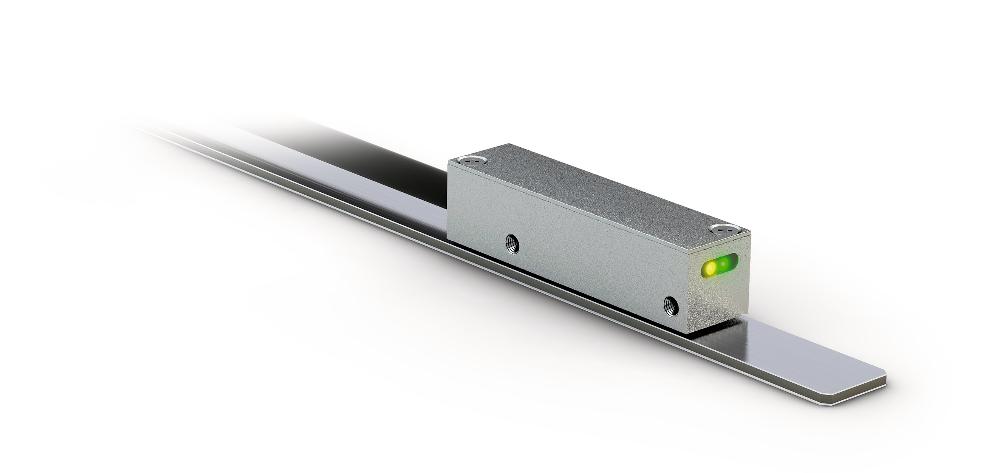
- Repeat accuracy max. ±1 μm
- Max. resolution 0.1 µm (LD output circuit)
- Reading distance 0.1 … 0.8 mm
- Works with MB160 magnetic tape
- Signal period 1600 μm
- Output circuit sin/cos or LD
- Function and status display LEDs

Ben
King
Inside Sales

Edward
Stuart
Product Manager Business Unit MagLine
Technical drawing

Technical Specifications
Mechanical data
Electrical data
System data
Ambient conditions
Feature
Technical Specifications
Enhancement
Weight
<0.03
kg
(without cable), cable 0.028 kg/m
Housing
zinc die-cast
Sensor/band reading distance
0.1 … 0.8 mm
O, I reference signals
0.1 … 0.5 mm
R reference signal
0.4 … 0.6 mm
FR reference signal
Cable sheath
PUR, suitable for drag-chain use
8-core ø4.3-0.4 mm
Cable bending radius
5x cable diameter
static
10x cable diameter
dynamic
Ausgangsschaltung LD
Feature
Technical Specifications
Enhancement
Operating voltage
5 V DC ±5 %
Current consumption
<50
mA
unloaded
<120
mA
loaded
Status display
2 LEDs
(yellow, green)
Output circuit
LD (RS422)
Output signals
A, /A, B, /B, I, /I, R, /R, FR, /FR
Output signal level high
>2.5
V
Output signal level low
<0.5
V
Latency
1.5
µs
Pulse width of reference signal
1
Increment(s)
,
2
,
4
Increment(s)
Type of connection
open cable end
Ausgang Sin/Cos
Feature
Technical Specifications
Enhancement
Operating voltage
5 V DC ±5 %
Current consumption
<35
mA
unloaded
<50
mA
loaded
Status display
2 LEDs
(yellow, green)
Output signals
sin, /sin, cos, /cos, index, /index
Output voltage
1 VPP ±10 %
at 0 … 70 °C
120 Ω teminal resistance
Signal period
1600
µm
Offset voltage
UB/2 ±100 mV
sine/cosine mean to GND (5 V DC)
Phasing
90°±1°, ±3° (20 kHz)
sin/cos
45
°
sin (reference signal)
135
°
cos (reference signal)
Pulse width of reference signal
180°±40°
Real-time requirement
speed-proportional signal output
Type of connection
open cable end
Signal pattern, Sin/Cos output
E: reference voltage 2.5 V
F: 1 VSS ±10 %
L: 180° ±40 %
M: 90° ±1.0° / ±3° (25 kHz)
X: 1 VSS
F: 1 VSS ±10 %
L: 180° ±40 %
M: 90° ±1.0° / ±3° (25 kHz)
X: 1 VSS
Signal pattern, LD output circuit
Note
The logic status of signals A and B is not defined regarding the reference signal FR. It may deviate from the signal pattern.
Note
Reference or index signal with 4 increments (360°) signal length is only valid from the 5th counting step onwards. A corresponding delay should be taken into consideration after switching on the operating voltage.
Pulse interval, LD output circuit
Feature
Technical Specifications
Enhancement
Resolution
0.1
µm
,
0.2
,
0.5
,
1
,
2
,
5
,
10
µm
LD output circuit
Linearity deviation
±3
µm
Repeat accuracy
±1
µm
0.3 mm reading distance
Measuring range
∞
Travel speed
≤25
m/s
sin/cos output, referencing speed ≤5 m/s
≤25
m/s
LD output circuit, see table,referencing speed ≤5 m/s
Travel speed
|
Travel speed Vmax [m/s] |
|||||||
|
Resolution [µm] |
0.1 |
0.80 |
0.40 |
0.32 |
0.16 |
0.08 |
0.04 |
|
0.2 |
1.60 |
0.80 |
0.64 |
0.32 |
0.16 |
0.08 |
|
|
0.5 |
4.00 |
2.00 |
1.60 |
0.80 |
0.40 |
0.20 |
|
|
1 |
8.00 |
4.00 |
3.20 |
1.60 |
0.80 |
0.40 |
|
|
2 |
16.00 |
8.00 |
6.40 |
3.20 |
1.60 |
0.80 |
|
|
5 |
25.00 |
20.00 |
16.00 |
8.00 |
4.00 |
2.00 |
|
|
10 |
25.00 |
25.00 |
25.00 |
16.00 |
8.00 |
4.00 |
|
|
Pulse interval [μs] |
0.10 |
0.20 |
0.25 |
0.50 |
1.00 |
2.00 |
|
|
Counting frequency [kHz] |
2500.00 |
1250.00 |
1000.00 |
500.00 |
250.00 |
125.00 |
|
|
3 |
1 |
2 |
2 |
2 |
2 |
2 |
2 |
Feature
Technical Specifications
Enhancement
Ambient temperature
-40 … 85 °C
Storage temperature
-40 … 85 °C
Relative humidity
100
%
condensation admissible
EMC
EN 61326-1
immunity requirement of industry
EN 61000-6-2
class B emission limit
Protection category
IP60
EN 60529
Shock resistance
≤500 m/s2, 11 ms
EN 60068-2-27, half-sine, 3 axes (+/-), each 3 shocks
Vibration resistance
≤100 m/s2, 10 Hz … 2000 Hz
EN 60068-2-6, 3 axes, each 10 cycles
More information
pin assignment
|
Signal Sin/Cos |
"Signal LD " |
Cable color |
|
sin |
A |
red |
|
cos |
/A |
yellow |
|
FR |
FR |
blue |
|
+UB |
+UB |
brown |
|
GND |
GND |
black |
|
/sin |
B |
orange |
|
/cos |
/B |
green |
|
/FR |
/FR |
violet |
Hint for mounting
For systems with reference points on the magnetic tape please take care that sensor and strip are correctly aligned (see picture).
|
Reference signal |
FR |
R |
O, I |
|
A, Sensor/tape reading distance |
0.4 … 0.6 mm |
0.1 … 0.5 mm |
0.1 … 0.8 mm |
|
B, Lateral offset |
±0.5 mm |
±0.5 mm |
±0.5 mm |
|
C, Alignment error |
±3° |
±3° |
±3° |
|
D, Longitudinal inclination |
±1° |
±1° |
±1° |
|
E, Lateral inclination |
±3° |
±3° |
±3° |
|
9 |
4 |
4 |
4 |
Symbolic representation
System components

Purchase order
Product configuration
Feature
Select specifications
Enhancement
Select your specifications:
Cable length
01.0
in m
Output circuit
1Vss
reference signal
O
Resolution
<leer>
only with 1Vss output circuit
in µm
Pulse interval
<leer>
only with 1Vss output circuit
in µs
Accessories
Scope of delivery
- LEC160
- Quick Start Guide