Magnetic sensor MSA213K
high-resolution absolute, numerous interfaces, swivel-mounted plug
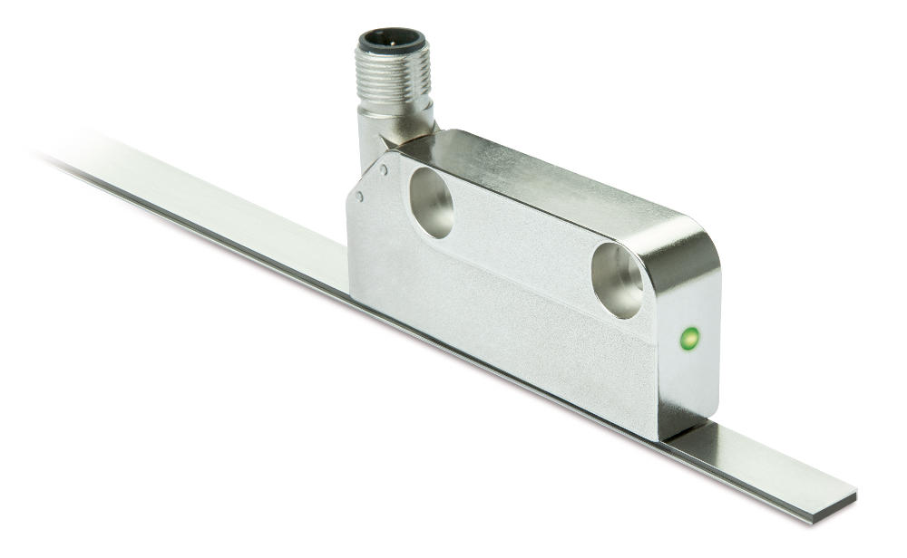
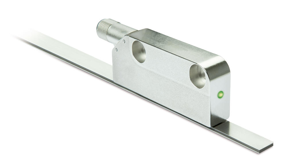

The absolute encoder MSA213K convinces with its high absolute resolution of 1 µm for precise position detection and a high reading distance of up to 0.8 mm at the same time. With the absolutely coded magnetic tape MBA213, measurements over a length of up to 16 meters are possible. Different absolute interfaces are available for integration into the control environment, which can be supplemented by incremental (LD) or analog (1 Vss) signal outputs for rapid regulation. The swivel-mounted M12 plug enables easy integration into the application on the customer side. The MSA213K is compatible with the MSA111C and can be used as an alternative with a higher reading distance and a longer absolute travel distance.
- High absolute resolution 1 μm
- Repeat accuracy max. ±1 μm
- Reading distance ≤0.8 mm
- Measuring range 0 … 16 m
- Function and status display LED
- Interface BiSS C, SSI, IO-Link
- Optionally analog Sin/Cos 1 Vss or digital line driver
- Connection technology M12 (A-coded), swivel-mounted
- Industry 4.0 ready

Ben
King
Inside Sales

Edward
Stuart
Product Manager Business Unit MagLine
Technical drawing

Technical Specifications
Mechanical data
Electrical data
System data
Ambient conditions
Feature
Technical Specifications
Enhancement
Weight
~0.095
kg
Housing
zinc die-cast
Sensor/band reading distance
≤0.8
mm
Feature
Technical Specifications
Enhancement
Operating voltage
7.5 … 30 V DC
reverse polarity protected (IOL)
4.5 … 30 V DC
reverse polarity protected (SSI + BISS/C)
Current consumption
200
mA
Status display
RGB-LED
Plausibility error, distance warning, device status
Output circuit
without, LD
Interface
SSI, BiSS C, IO-Link
Type of connection
M12 plug connector (A-coded)
12-pole, 1x pin (IOL)
M12 plug connector (A-coded)
4-pole, 1x pin (IOL)
Signal pattern, Sin/Cos output
E: reference voltage 2.5 V
F: 1 VSS ±10 %
M: 90° ±1.0° / ±3° (25 kHz)
F: 1 VSS ±10 %
M: 90° ±1.0° / ±3° (25 kHz)
Signal pattern, LD output circuit
Pulse interval, LD output circuit
Feature
Technical Specifications
Enhancement
Pole length
2
mm
incremental
Resolution
1
µm
absolute
1
µm
,
5
,
10
µm
LD, incremental
Linearity deviation
±10
µm
Repeat accuracy
±1
µm
Measuring range
≤16384
mm
Travel speed
≤5
m/s
absolute
Travel speed
|
Travel speed Vmax [m/s] |
|||||||
|
Resolution [µm] |
1 |
10.00 |
5.00 |
2.00 |
1.00 |
0.50 |
0.20 |
|
5 |
25.00 |
25.00 |
10.00 |
5.00 |
2.50 |
1.00 |
|
|
10 |
25.00 |
25.00 |
20.00 |
10.00 |
5.00 |
2.00 |
|
|
Pulse interval [μs] |
0.10 |
0.20 |
0.50 |
1.00 |
2.00 |
5.00 |
|
|
Counting frequency [kHz] |
2500.00 |
1250.00 |
500.00 |
250.00 |
125.00 |
50.00 |
|
|
3 |
1 |
2 |
2 |
2 |
2 |
2 |
2 |
Feature
Technical Specifications
Enhancement
Ambient temperature
-40 … 85 °C
Storage temperature
-40 … 85 °C
Relative humidity
100
%
condensation admissible
EMC
EN 61000-6-2
interference resistance / immission, class B emission limit
EN 61000-6-4
interference emission / emission, class B emission limit
Protection category
IP67
EN 60529, with mating connector fitted
Shock resistance
≤500 m/s2, 11 ms
EN 60068-2-27, half-sine, 3 axes (+/-), each 3 shocks
Vibration resistance
≤100 m/s2, 10 Hz … 2000 Hz
EN 60068-2-6, 3 axes, each 10 cycles
More information
pin assignment
SSI, BiSS C interface without LD, 1 Vss
|
SSI |
BiSS C |
PIN |
|
nc |
nc |
1 |
|
D+ |
SLO |
2 |
|
D- |
NSLO |
3 |
|
T- |
NMA |
4 |
|
+UB |
+UB |
5 |
|
nc |
nc |
6 |
|
nc |
nc |
7 |
|
nc |
nc |
8 |
|
nc |
nc |
9 |
|
nc |
nc |
10 |
|
T+ |
MA |
11 |
|
GND |
GND |
12 |
SSI, BiSS C interface with LD, 1 Vss
|
SSI |
BiSS C |
PIN |
|
nc |
nc |
1 |
|
D+ |
SLO |
2 |
|
D- |
NSLO |
3 |
|
T- |
NMA |
4 |
|
+UB |
+UB |
5 |
|
/A, Sin- |
/A, Sin- |
6 |
|
A, Sin+ |
A, Sin+ |
7 |
|
/B, Cos- |
/B, Cos- |
8 |
|
B, Cos+ |
B, Cos+ |
9 |
|
nc |
nc |
10 |
|
T+ |
MA |
11 |
|
GND |
GND |
12 |
IO-Link interface without LD, 1 Vss
|
Signal |
PIN |
|
L+ (+UB) |
1 |
|
I/Q |
2 |
|
L- (GND) |
3 |
|
C/Q |
4 |
IO-Link interface with LD, 1 Vss
|
Signal |
PIN |
|
nc |
1 |
|
nc |
2 |
|
nc |
3 |
|
nc |
4 |
|
L+ (+UB) |
5 |
|
/A, Sin- |
6 |
|
A, Sin+ |
7 |
|
/B, Cos- |
8 |
|
B, Cos+ |
9 |
|
C/Q |
10 |
|
I/Q |
11 |
|
L- (GND) |
12 |
Industry 4.0
In most cases, data exchange with the magnetic encoders is limited to the exchange of process data. In addition to the process data, intelligent drives provide additional information that can be evaluated for condition monitoring up to predictive maintenance:
|
Process data |
Smart Value |
Smart Function |
|
Actual position |
-- |
Plausibility monitoring |
Hint for mounting
When mounting sensor and magnetic tape, please be careful to align both system components correctly. The arrow marks on the tape and sensor must point in the same direction when mounting the components.
|
A, Sensor/tape reading distance |
≤0.8 mm |
|
B, Lateral offset |
±0.6 mm |
|
C, Alignment error |
±1° |
|
D, Longitudinal inclination |
max. sensor/tape A reading distance must never be exceeded. |
|
E, Lateral inclination |
max. sensor/tape A reading distance must never be exceeded. |
Symbolic representation
System components


Purchase order
Product configuration
Feature
Select specifications
Enhancement
Select your specifications:
incremental resolution
1
in µm
Pulse interval
0.1
in µs


Scope of delivery
- MSA213K
- Distance gage
- Quick Start Guide