Magnetic sensor MSK1000
Incremental, digital interface, resolution 0.2 μm
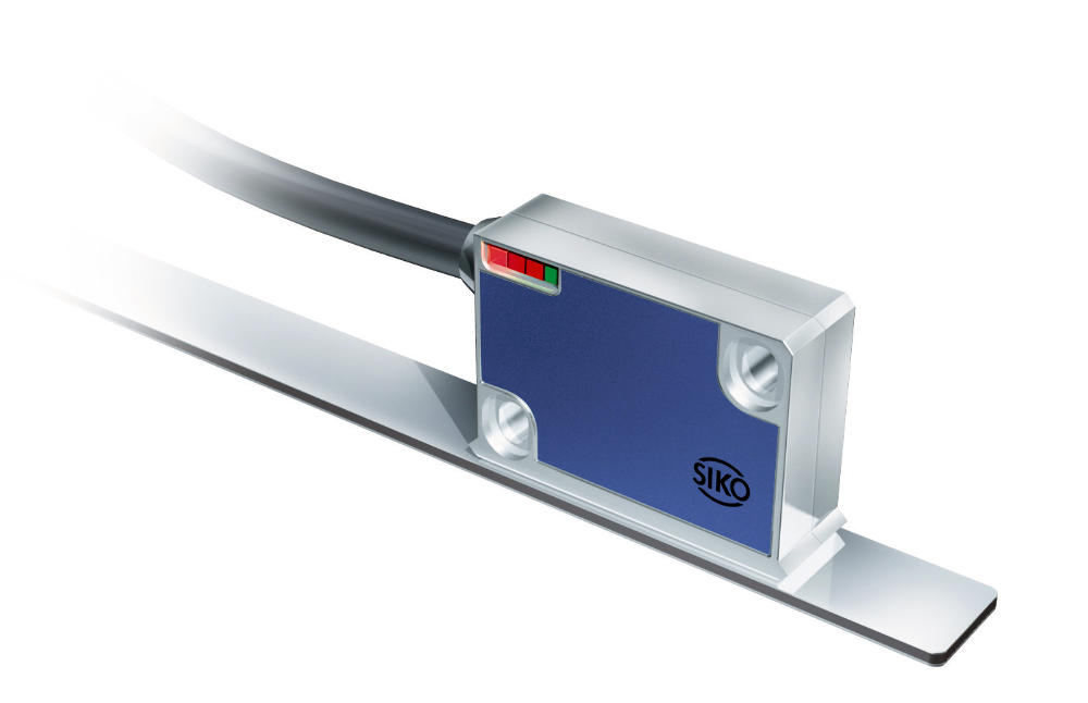
- Max. resolution 0.2 μm
- Repeat accuracy ±1 μm
- LED status display
- Reading distance ≤0.4 mm
- Robust metal housing


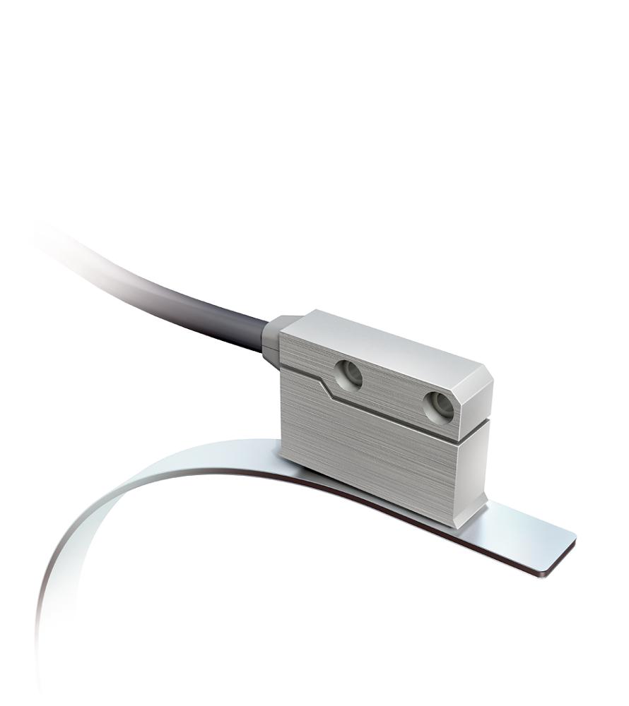
Technical drawing

Technical Specifications
Travel speed
|
Travel speed Vmax [m/s] |
|||||
|
Resolution [µm] |
0.2 |
0.64 |
0.32 |
0.16 |
0.08 |
|
1 |
3.20 |
1.60 |
0.80 |
0.40 |
|
|
2 |
6.40 |
3.20 |
1.60 |
0.80 |
|
|
5 |
16.00 |
8.00 |
4.00 |
2.00 |
|
|
Pulse interval [μs] |
0.25 |
0.50 |
1.00 |
2.00 |
|
|
Counting frequency [kHz] |
1000.00 |
500.00 |
250.00 |
125.00 |
|
|
3 |
1 |
3 |
3 |
3 |
3 |
Signal image
Note
The logical condition of signals A and B is not defined in reference to the index signal I or the reference signal R. It can deviate from the signal form.
Note
Reference or index signal with 4 increments (360°) signal length is only valid from the 5th counting step onwards. A corresponding delay should be taken into consideration after switching on the operating voltage.
Pulse interval, LD output circuit
More information
pin assignment
Inverted without reference signal
|
Signal |
E1 |
E6X |
E8X |
|
A |
red |
1 |
1 |
|
B |
orange |
2 |
2 |
|
nc |
3 |
3 |
|
|
+UB |
brown |
4 |
4 |
|
GND |
black |
5 |
5 |
|
/A |
yellow |
6 |
6 |
|
/B |
green |
7 |
7 |
|
nc |
8 |
||
|
nc |
9 |
Inverted with reference signal
|
Signal |
E1 |
E6X |
E8X |
|
A |
red |
1 |
1 |
|
B |
orange |
2 |
2 |
|
I,R |
blue |
3 |
3 |
|
+UB |
brown |
4 |
4 |
|
GND |
black |
5 |
5 |
|
/A |
yellow |
6 |
6 |
|
/B |
green |
7 |
7 |
|
/I, /R |
violet |
8 |
8 |
|
nc |
9 |
Hint for mounting
|
Reference signal |
O, I |
R |
|
A, Sensor/tape reading distance |
≤0.4 mm |
≤0.2 mm |
|
B, Lateral offset |
±2 mm |
±0.5 mm |
|
C, Alignment error |
±3° |
±3° |
|
D, Longitudinal inclination |
±1° |
±1° |
|
E, Lateral inclination |
±3° |
±3° |
|
3 |
2 |
2 |
System components


Purchase order
Product configuration
Feature
Select specifications
Enhancement
Operating voltage
10
design
M
Type of connection
E1
Cable length
01.0
reference signal
O
Resolution
0.2
Pulse interval
0.25

Scope of delivery
- MSK1000
- Fastening set
- Installation Instructions


